 |
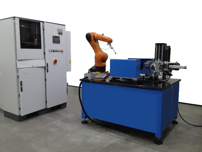
Automatic station for 100% cracks control on brake discs and brake drums |
Innovative system for the control of cracks for brake discs and brake drums, based on Eddy Current technology:
• Greatest flexibility for the management of control cycles.
• Greatest velocity for the type change.
• Minimum costs for retooling.
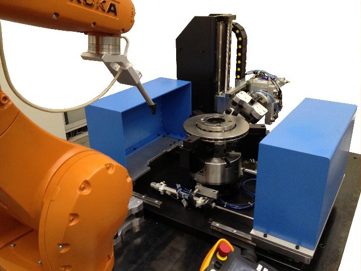
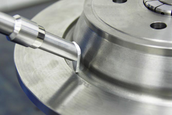
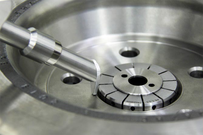
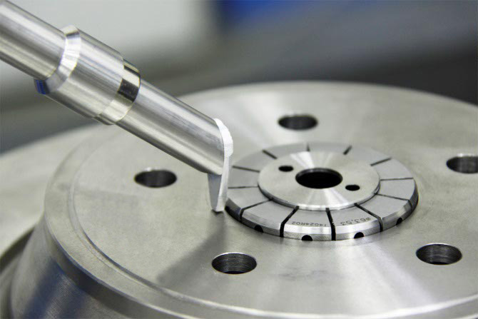
• Locking of the disc on the centring hole with elastic pliers or on the external diameter with 3 jaw pliers.
• Possibility to check discs coming from different lines.
• Possibility to change the measuring program at each piece.
• Simplicity of dialogue with the line.
• Outputs totally configurable.
• Load/Unload with robot, manual or with specific systems.
• Automatic management of master verification.
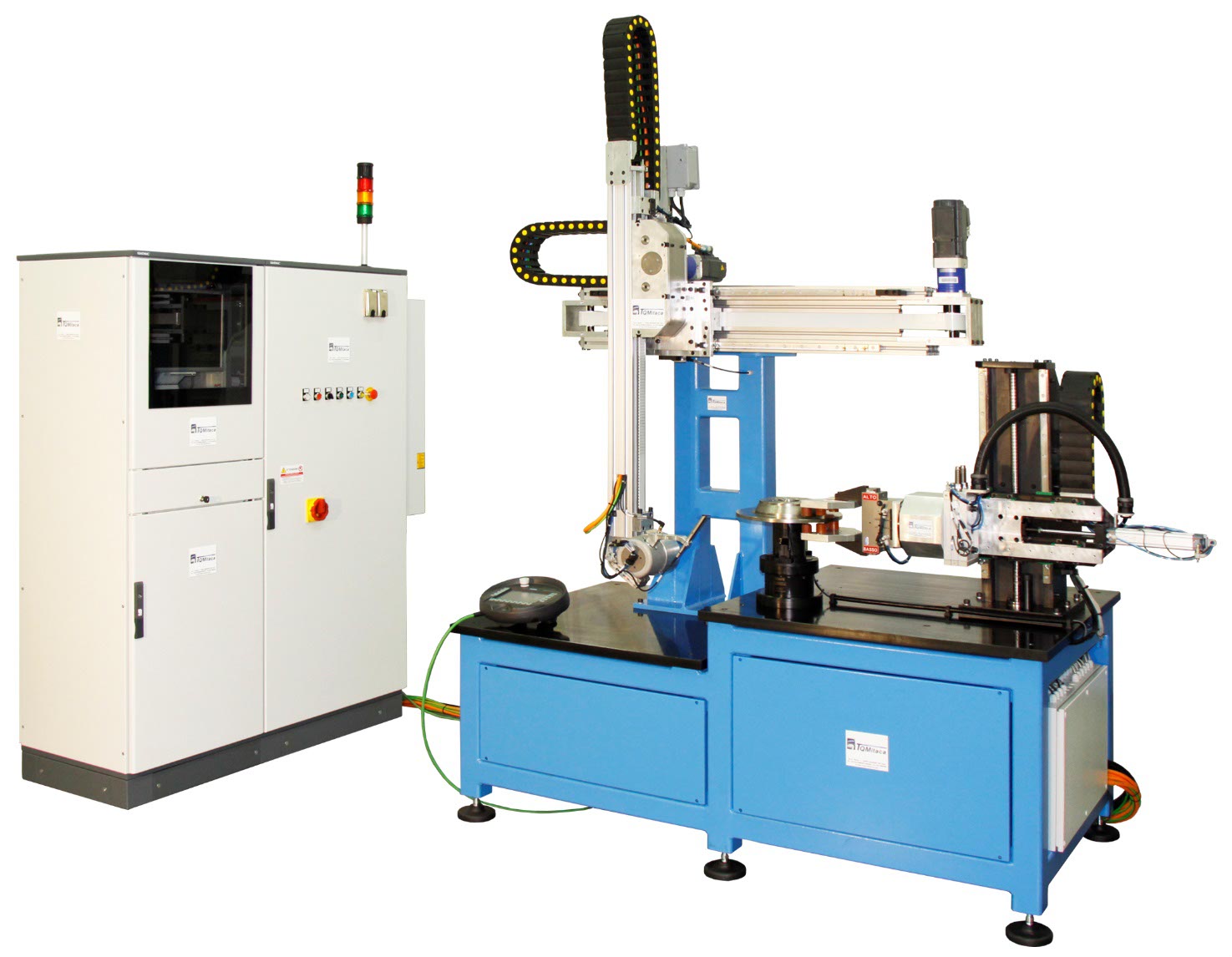
Different mechanic configurations are available, according to the requested control plan and to the type of the production line. The probe movement can be managed by a precision robot or by Cartesian manipulator. Both solutions allow maximum flexibility and simplicity for the management of the type change and for modifications to the control plan: the addition of a new zone to be controlled will demand only the modification of the probe path. In case of stations with manual load/unload, are provided protections and barriers.
 |
 |
 |
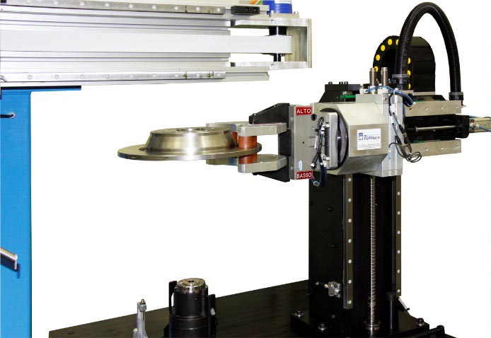 |
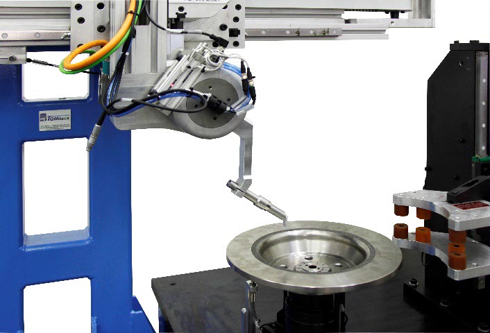
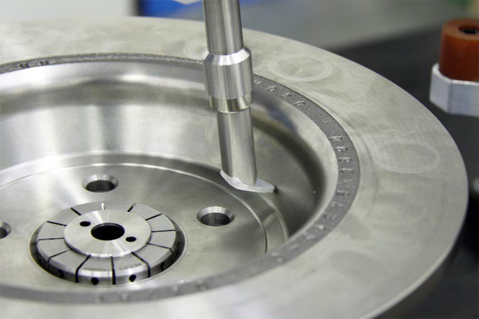
If it is necessary to control also the support plane, the bench will be equipped with an automatic tilter.
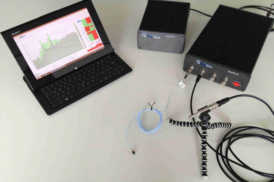
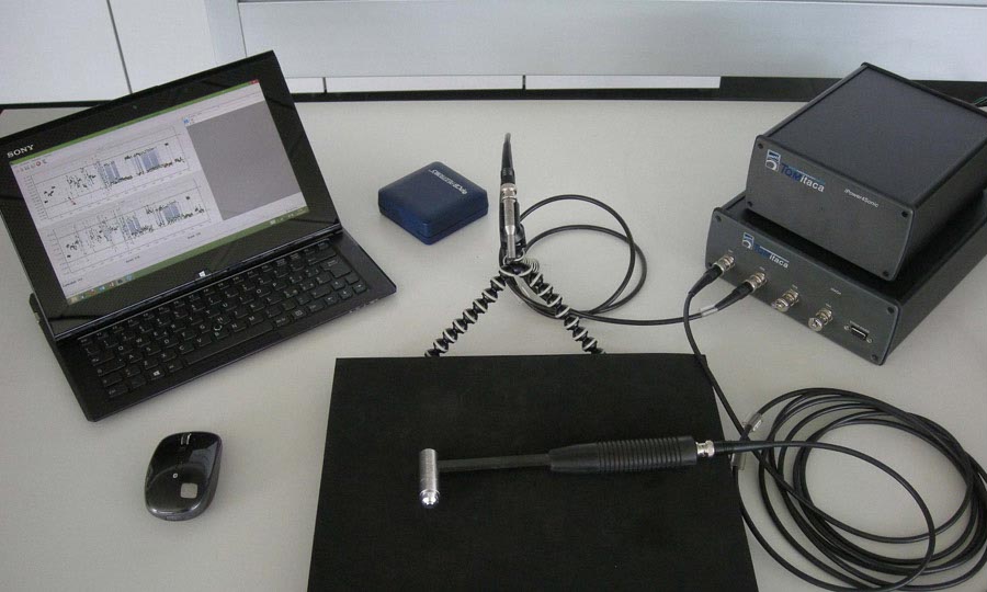
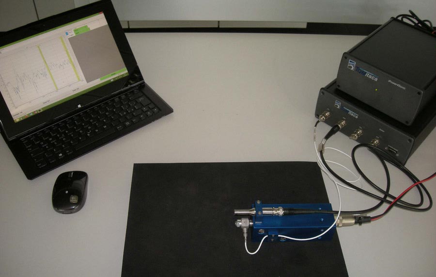
The station is composed of:
• Double electrical cabinet with air cooler
• PC with monitor, keyboard, mouse
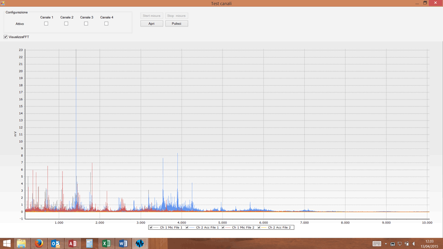
• Software Itanoise©
• 1 channel Eddy Current instrument
• Bench in painted heavy carpentry
• Precision mandrel with adjustable rotation speed (up to 1.200 turns/min)
• Cartesian manipulator with electric axes, wrist with rotation
• Tilter (option)
The bench is modular, it can be integrated in an existing line and it’s possible to add the sonic control (elevator + Itasonic 2010© system), it’s possible to manage the generation of a serial number in case of good piece and the dispatch of the same to a marking system.
The mode of manage of the probe allows to easily reach all the areas demanded by the control plan.
 |
 |
 |
 |
The cycle time depends on the number and on the dimension of the areas to be controlled. The total control on the rotation speed of the disc (up to 1.200 turns/min) and on the speed of the axis of the manipulator allows to reduce the control times.
The type change can demand the substitution of the locking pliers and/or of the support plate: this operation demands only few minutes.
The bench is managed by the software Itamatic©, specifically developed in order to simplify the management of complex benches, equipped with control systems made by third party and with management of movement. The logic of management is the same of Itageo 6©, Itastat 6, Itasonic 2010©, etc... with control plans and measuring batches.
The data are saved in the Itastat/Itageo database.
Software Itamatic© - Main features
• Simple and intuitive.
• Logic structure as in Itageo 6©, Itasonic 2010©, Itastat 6, with batches and measuring programs.
• Data saved in Itastat6 database in SQL format.
• Users management with operator permissions.
• Auxiliary Data management.
• S/N management.
• Traceability management.
• Master verification management.
• Guided creation of the control plans – measuring programs, where define all the parameters of the test.
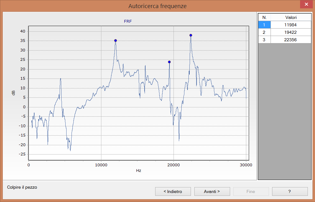
• Permission to integrate also other software for example Itasonic 2010© for FRF control.
• Large possibility to personalize the user interface.
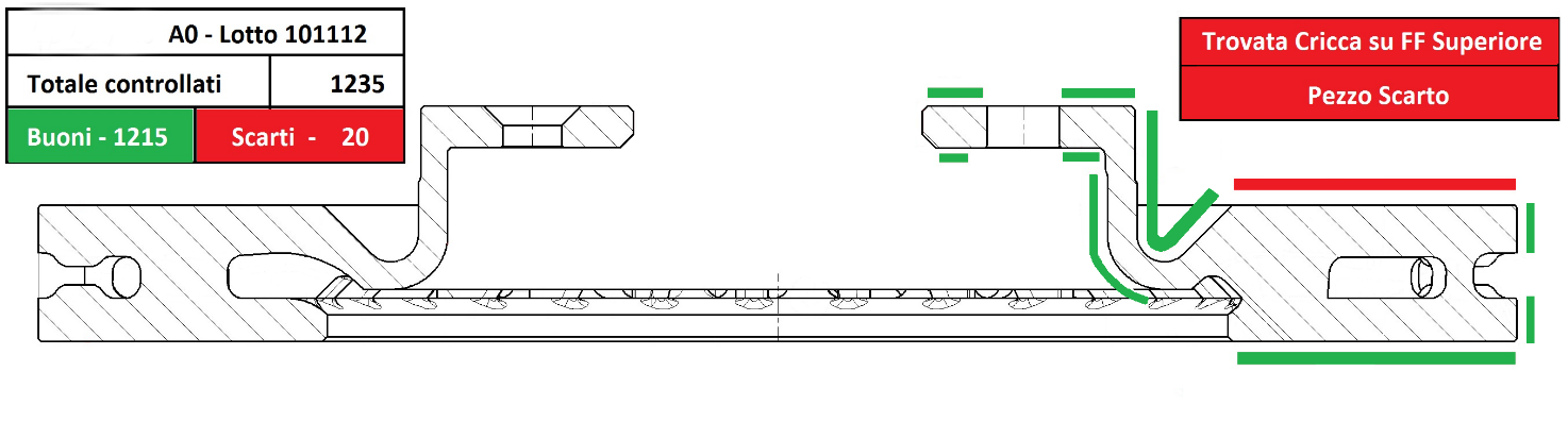
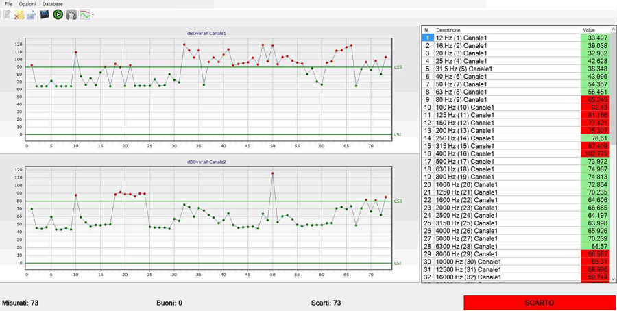
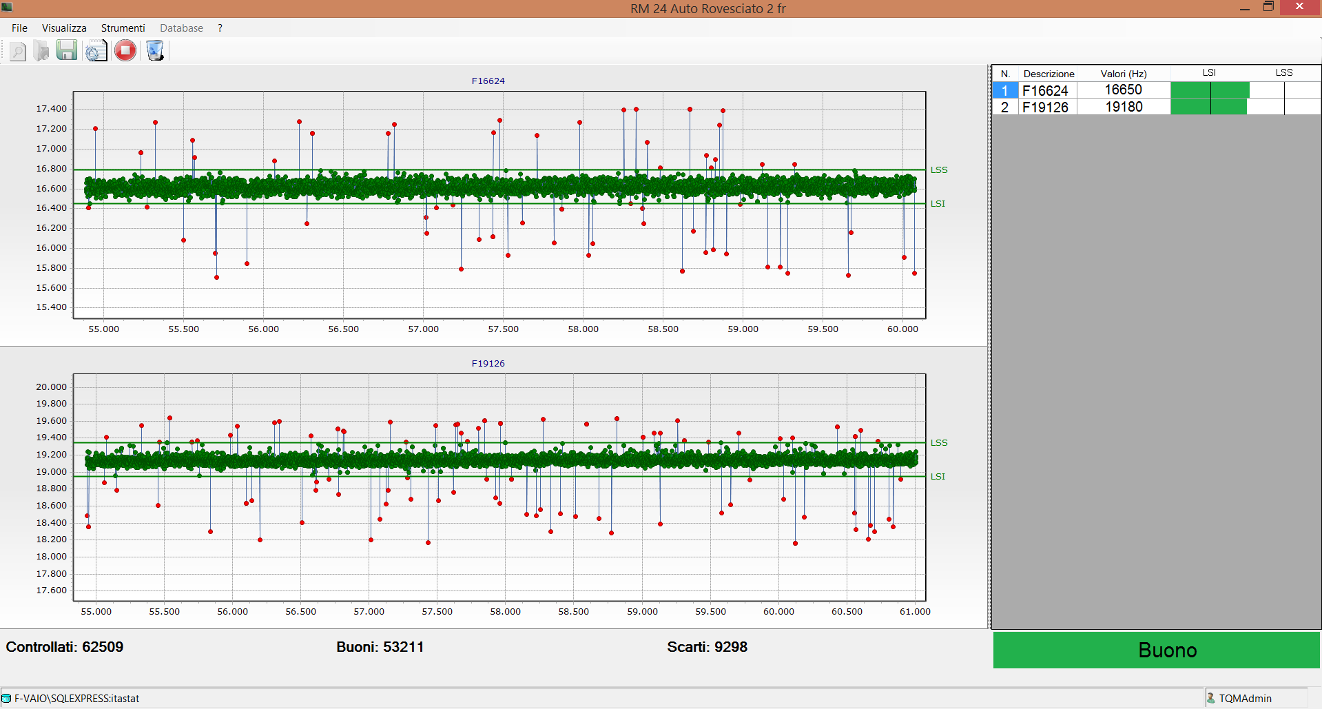
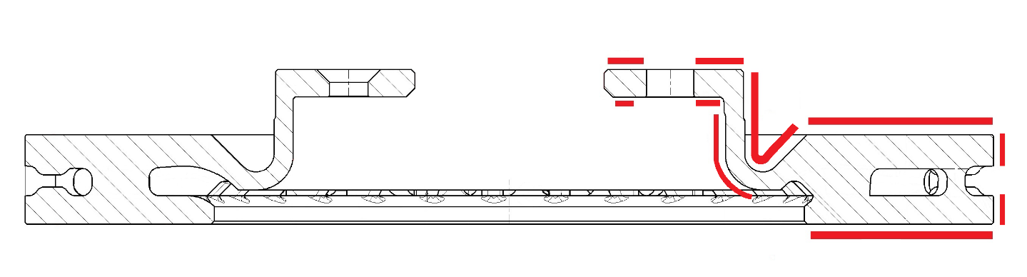
Example of a control plan of brake discs
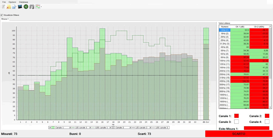
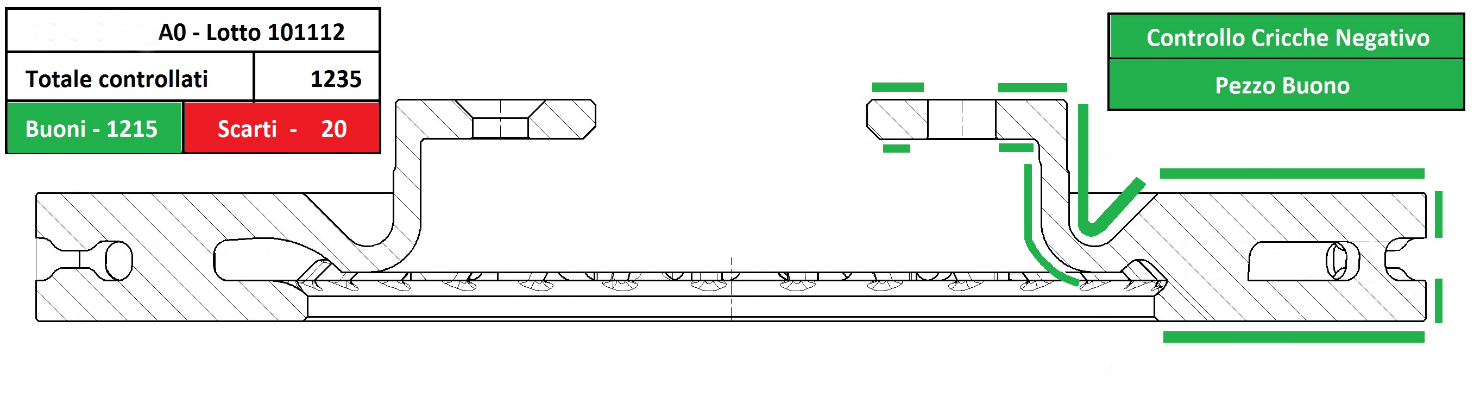
Example of a screen in case of disc without cracks.
Good piece
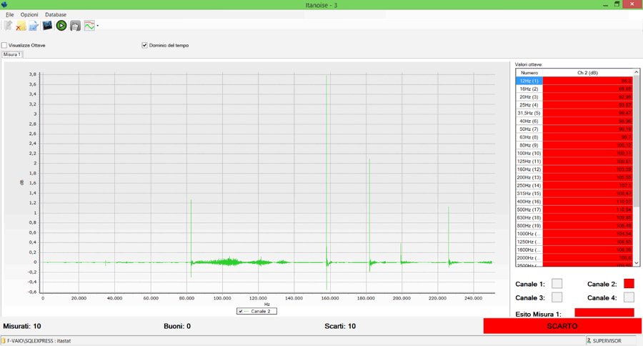
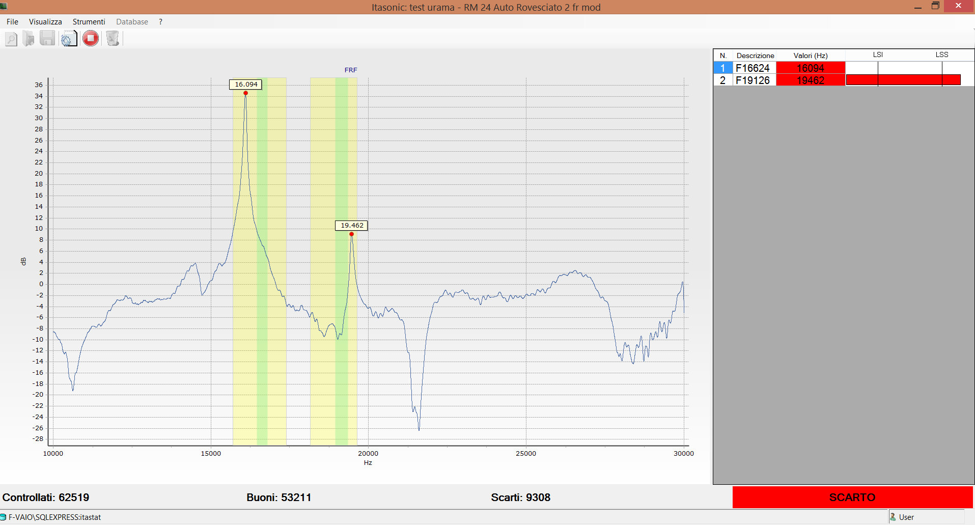
Example of a screen in case of a disc with a crack detected on the upper braking surface.
Rejected piece